Power Electronics Testing Systems Information With Measurement Technology and Engineering Details
Power Electronics Testing Systems are specialized arrangements of instruments, software, and electrical equipment used to evaluate how electronic circuits and devices control electrical energy.
These systems examine the performance, efficiency, stability, and safety-related characteristics of components that convert electrical power from one form to another.
Power electronics is used in electric vehicles, renewable energy installations, industrial machinery, battery systems, computers, and household appliances. Common examples of power electronic equipment include inverters, rectifiers, DC-DC converters, motor drives, and power supplies. Testing helps engineers understand how these devices behave under different electrical loads and operating conditions.
The development of modern power electronics testing is closely connected to advances in semiconductor technology. Components such as insulated-gate bipolar transistors (IGBTs) and silicon carbide (SiC) and gallium nitride (GaN) devices can switch electrical power rapidly. Their behavior requires measurement systems capable of capturing voltage, current, switching transitions, temperature, and electrical losses.
Main Components of a Testing System
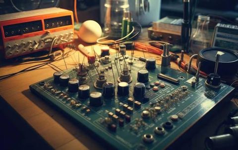
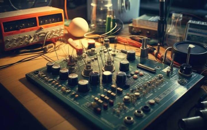
A power electronics test bench combines measurement instruments, controlled power sources, loads, safety equipment, and data acquisition software. Each element has a defined role in collecting information about the device under examination.
Typical components include:
Programmable power supplies that provide controlled input voltage and current.
Electronic loads that reproduce different operating demands.
Oscilloscopes that display electrical signals over time.
Voltage and current probes that measure circuit behavior.
Power analyzers that calculate active power, power factor, and efficiency.
Temperature sensors that monitor component heating.
Data acquisition systems that record measurements for later analysis.
Some installations also use regenerative power equipment, which can return a portion of consumed electrical energy to the supply system. The exact arrangement depends on the device rating, test objectives, and required measurement accuracy.
Types of Power Electronics Testing
Different tests examine different aspects of electrical performance. Functional testing checks whether a converter operates according to its intended design, while efficiency testing compares electrical input and output power.
Switching characterization examines how quickly semiconductor devices change states and how much energy is lost during those transitions. Thermal testing measures temperature changes during operation, while electromagnetic compatibility testing evaluates unwanted electrical emissions and immunity to external disturbances.
Importance
Improving Electrical Performance
Power electronics testing systems help engineers identify losses, unstable behavior, excessive heating, and unexpected voltage or current fluctuations. These issues can affect equipment reliability, operating efficiency, and the performance of connected electrical systems.
For example, an inverter used in a solar installation must convert direct current into alternating current with appropriate electrical characteristics. Testing can reveal conversion losses, waveform distortion, and changes in performance when the input voltage or load varies.
Supporting Multiple Industries
Testing systems are relevant to several industries because electronic power conversion is used across a wide range of applications.
Electric mobility: evaluating traction inverters, onboard chargers, and DC-DC converters.
Renewable energy: examining solar inverters, battery converters, and grid-interactive equipment.
Industrial automation: testing variable-frequency drives and motor controllers.
Energy storage: assessing battery charging and discharging equipment.
Consumer electronics: evaluating adapters, chargers, and power supply circuits.
Aerospace and transportation: measuring power conversion performance under defined operating conditions.
Reducing Engineering Uncertainty
Electrical devices may behave differently under steady loads, sudden load changes, elevated temperatures, or abnormal operating conditions. Laboratory testing allows engineers to examine these variations in a controlled environment before equipment is integrated into a larger system.
Measurement quality is particularly important. Incorrect probe connections, unsuitable instrument bandwidth, poor grounding, or calibration errors can produce misleading results. Engineers therefore consider instrument specifications, test procedures, environmental conditions, and measurement uncertainty when interpreting data.
Recent Updates
Wide-Bandgap Semiconductor Testing
Power electronics development increasingly includes silicon carbide and gallium nitride semiconductors. Compared with conventional silicon devices in suitable applications, these technologies can support higher switching frequencies or improved efficiency, depending on device design and operating conditions.
Their fast switching behavior also creates measurement challenges. Voltage transitions can occur over very short intervals, making probe bandwidth, common-mode rejection, connection layout, and timing accuracy important factors in test system design.
Digital Testing and Automated Measurement
Automated testing has become an important part of power electronics engineering. Programmable instruments and software can coordinate voltage sources, electronic loads, measurement devices, and test sequences while recording results consistently.
Automation can help engineers repeat tests across different operating points and compare results between prototypes. However, automated procedures still require appropriate limits, verified measurement configurations, and review of unexpected results.
Real-Time Simulation and Hardware-in-the-Loop
Hardware-in-the-loop testing connects physical controllers or electronic hardware to a real-time simulation of a larger electrical system. For example, a motor controller can be evaluated against a simulated motor and vehicle model before a complete physical assembly is available.
This method supports testing of control responses, operating transitions, and selected fault scenarios. It does not replace every physical test because simulated models may not reproduce all thermal, electromagnetic, mechanical, or component-level effects.
Trends in Measurement Technology
Recent engineering developments emphasize higher measurement bandwidth, improved synchronization, automated data analysis, and more flexible testing arrangements. Modular test equipment can also make it easier to adapt a laboratory setup for different converter designs.
The growth of renewable energy, electrified transportation, and battery storage continues to increase the need for testing methods that examine efficiency, dynamic response, thermal behavior, and compatibility with connected systems.
Laws or Policies
Electrical Safety Requirements
Power electronics testing systems must be designed and operated with attention to electrical hazards. High voltage, high current, stored capacitor energy, hot components, and rotating equipment can create serious risks.
Applicable safety requirements depend on the country, equipment category, laboratory environment, and intended use. Common safety practices include protective enclosures, interlocks, emergency shutdown controls, grounding arrangements, discharge procedures, and clearly defined operating limits.
Personnel should understand the equipment and follow established laboratory procedures. High-energy testing requires appropriate engineering controls and qualified supervision.
Measurement Standards and Calibration
Electrical measurement instruments may be evaluated against recognized standards and calibration procedures. Calibration helps establish the relationship between an instrument's indicated values and reference measurements, along with relevant uncertainty information.
For power analyzers, oscilloscopes, voltage probes, and current sensors, calibration status and instrument specifications influence the confidence that can be placed in recorded results. A calibration certificate does not automatically mean that an instrument is suitable for every measurement task.
Electromagnetic Compatibility and Product Compliance
Electronic equipment may need to meet electromagnetic compatibility requirements before being placed on particular markets. These requirements generally address electromagnetic emissions and the ability to operate in the presence of specified disturbances.
Depending on the application, engineers may also need to consider electrical safety, energy efficiency, environmental requirements, and grid-connection rules. The relevant conformity assessment depends on the product and jurisdiction, so a single testing procedure does not establish compliance with every applicable requirement.
Tools and Resources
Essential Measurement Instruments
Selecting instruments begins with understanding the electrical signals and operating range of the device under test. Voltage rating, current capacity, frequency range, measurement bandwidth, accuracy, and isolation requirements all influence instrument selection.
The following table summarizes common equipment used in power electronics testing.
Instrument | Main function | Typical measurement |
|---|---|---|
Oscilloscope | Displays signals over time | Switching waveforms and transients |
Power analyzer | Measures electrical power | Input power, output power, efficiency |
Differential voltage probe | Measures voltage between two points | Converter switching voltage |
Current probe | Measures current flow | Switching and load current |
Electronic load | Applies controlled electrical demand | Converter output performance |
Programmable power supply | Provides controlled input power | Voltage and current response |
Thermal camera | Displays surface temperature patterns | Heating and thermal distribution |
Data acquisition system | Records measurement data | Long-duration performance trends |
Engineering Calculations
Several basic calculations help interpret test results. For a system operating under suitable measurement conditions, efficiency can be calculated by dividing output power by input power and multiplying by 100.
For example, if a converter receives 1,000 watts and delivers 950 watts, its measured conversion efficiency is 95%. The difference represents 50 watts of power loss under those test conditions, although measurement uncertainty should be considered.
Other useful calculations include power factor, voltage ripple, current ripple, switching frequency, and total harmonic distortion. The appropriate calculation depends on whether the system uses direct current, alternating current, or a combination of both.
Software and Test Documentation
Test software can coordinate instrument settings, automate measurement sequences, and store results in structured formats. Engineers may use waveform analysis programs, circuit simulation tools, numerical computing environments, and manufacturer-provided instrument software.
A clear test record typically contains:
Device identification and configuration.
Test objectives and operating conditions.
Instrument models and calibration status.
Wiring and probe arrangements.
Recorded voltage, current, power, and temperature.
Measurement uncertainty and relevant limitations.
Deviations, observations, and final results.
Consistent documentation helps teams compare prototypes, investigate unexpected results, and reproduce test conditions during later engineering work.
FAQs
What are power electronics testing systems used for?
They evaluate electrical performance, conversion efficiency, switching behavior, temperature, and selected safety-related characteristics of devices such as inverters, rectifiers, converters, and motor drives.
Which instruments are used in power electronics testing?
Common instruments include oscilloscopes, power analyzers, differential voltage probes, current probes, programmable power supplies, electronic loads, and data acquisition systems.
How is efficiency measured in a power electronics testing system?
Efficiency is calculated by dividing measured output power by measured input power and multiplying the result by 100. Accurate measurements require suitable instruments and consistent operating conditions.
Why is wide-bandgap semiconductor testing important?
Silicon carbide and gallium nitride devices can switch rapidly, creating demanding measurement conditions. Appropriate bandwidth, probe selection, connection layout, and timing accuracy help engineers characterize their behavior.
What standards apply to power electronics testing systems?
Applicable requirements depend on the equipment, application, and jurisdiction. Electrical safety, measurement calibration, electromagnetic compatibility, and product-specific conformity requirements may all be relevant.
Conclusion
Power electronics testing systems combine measurement instruments, controlled electrical sources, loads, and software to evaluate power conversion equipment. Advances in semiconductor technology and automated testing are increasing the importance of accurate, synchronized measurements. Safety procedures, calibration, and appropriate test methods remain essential for producing reliable engineering data. The resulting measurements help engineers assess performance, investigate design limitations, and document equipment behavior under defined conditions.