Industrial 3D Metrology Systems Guide: Scanners, Sensors, Measurement Methods and Applications
An Industrial 3D Metrology Systems Guide explains how three-dimensional scanning equipment, optical sensors, measurement methods, and digital analysis tools are used to measure physical objects. Industrial 3D metrology combines measurement science with technologies that capture an object's dimensions, shape, surface details, and geometric relationships.
Context
An Industrial 3D Metrology Systems Guide explains how three-dimensional scanning equipment, optical sensors, measurement methods, and digital analysis tools are used to measure physical objects. Industrial 3D metrology combines measurement science with technologies that capture an object's dimensions, shape, surface details, and geometric relationships. It is used in manufacturing, engineering, automotive production, aerospace, electronics, and other industries where dimensional accuracy matters.
Traditional measurement methods often rely on rulers, gauges, coordinate measuring machines, or specialized instruments that examine selected points on a component. Industrial 3D metrology systems can collect thousands or millions of measurement points, depending on the equipment and application. These measurements can be processed into a digital representation that engineers use to examine shapes, compare parts with design models, and identify dimensional differences.
Understanding Industrial 3D Metrology Systems
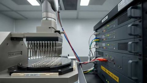
A typical system includes measurement hardware, data-processing software, calibration procedures, and a method for positioning the object or sensor. Some systems capture measurements without touching the surface, while others use a physical probe to measure specific locations.
Common technologies include laser 3D scanners, structured-light scanners, optical measurement sensors, and coordinate measuring machines. The appropriate technology depends on the object's size, surface properties, required accuracy, inspection environment, and measurement task.
Main Components and Functions
Industrial 3D metrology systems generally contain several elements:
Scanner or sensor: Captures surface information or dimensional measurements.
Positioning equipment: Includes tripods, robotic arms, rotary tables, or machine axes that help collect measurements from different directions.
Calibration references: Known standards or artifacts used to check measurement performance.
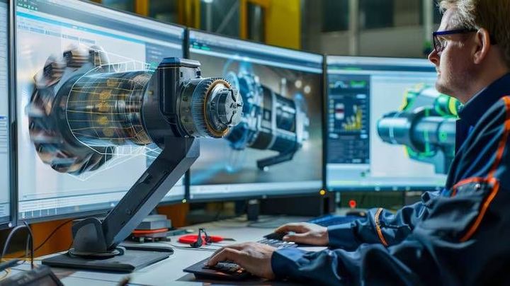
Data-processing software: Converts measurement data into point clouds, meshes, or dimensional reports.
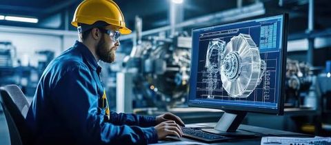
Inspection software: Compares measured geometry with engineering drawings, CAD models, or specified tolerances.
These components work together to transform physical measurements into information that production and quality teams can interpret. The complete measurement process also depends on correct setup, environmental conditions, and appropriate measurement procedures.
Importance
Industrial 3D metrology matters because small dimensional differences can affect how manufactured components fit, move, connect, or perform. In automotive manufacturing, for example, measurements may help verify body panels and mechanical components. In aerospace production, dimensional inspection can help determine whether parts match engineering specifications.
The technology also supports product development, reverse engineering, maintenance, and quality control. Engineers can examine an existing component, create a digital representation of its geometry, and use that information during redesign or replacement planning. However, a scan alone does not establish a material's internal condition or prove that a component meets every functional requirement.
Applications Across Industries
Industrial 3D metrology systems are used in a range of manufacturing and engineering activities.
Automotive production: Measuring body panels, engine components, moulds, and assembly fixtures.
Aerospace engineering: Inspecting complex surfaces, structural components, and precision assemblies.
Machine manufacturing: Checking machined parts, tooling, gears, and industrial equipment.
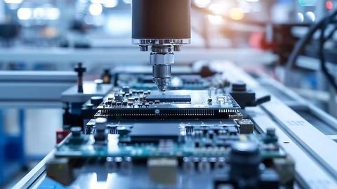
Electronics production: Measuring small housings, connectors, circuit-board features, and component placement.
Medical device manufacturing: Inspecting external geometry and dimensions where the applicable quality requirements permit.
Energy and heavy industry: Measuring turbines, pipes, large structures, and equipment components.
Comparing Measurement Technologies
Different measurement methods have different strengths and limitations. The following table summarizes common industrial options.
| Technology | Measurement method | Typical applications | Main consideration |
|---|---|---|---|
| Laser 3D scanner | Captures surface points using laser-based sensing | Complex parts, tooling, dimensional inspection | Surface finish and scanning conditions |
| Structured-light scanner | Projects a light pattern and observes its deformation | Detailed surface capture and product development | Lighting and reflective surfaces |
| Coordinate measuring machine (CMM) | Uses a probe to measure defined points | Precision dimensional inspection | Access, setup, and measurement time |
| Optical measurement sensor | Uses imaging or other optical principles | Small components and production inspection | Visibility and surface characteristics |
| Laser tracker | Tracks a measurement target in three-dimensional space | Large assemblies and industrial alignment | Line of sight and environmental conditions |
| Photogrammetry | Calculates geometry from multiple photographs | Large objects and complex structures | Image quality and reference control |
No single technology suits every application. A system's stated accuracy should be interpreted alongside its measurement volume, calibration status, uncertainty, operating conditions, and the method used to evaluate results.
Understanding Accuracy, Precision, and Tolerance
Accuracy describes how close a measurement is to the relevant reference value, while precision concerns the consistency of repeated measurements. Tolerance defines the permitted range of variation for a specified dimension or feature. These concepts are related but not interchangeable.
For example, a component may have a dimensional tolerance of ±0.1 millimetres. The inspection method must be capable of assessing that tolerance with suitable measurement uncertainty. A scanner's advertised resolution does not, by itself, establish its measurement accuracy or its suitability for the task.
Recent Updates
Industrial 3D metrology has continued to develop through improvements in sensor design, software processing, automation, and integration with digital manufacturing systems. Trends across 2024–2026 include greater use of automated inspection, more rapid processing of complex scan data, and increased integration between measurement equipment and production workflows. The features available depend on the equipment manufacturer, software version, and application.
Automated Inspection and Robotics
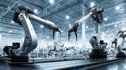
Robotic scanning systems combine 3D sensors with industrial robot arms or automated positioning equipment. These arrangements can collect measurements from multiple angles and support repeated inspection tasks within manufacturing environments.
Automation can reduce repetitive manual handling and help standardize data collection. However, reliable results still depend on robot calibration, sensor alignment, part positioning, environmental stability, and suitable inspection programming. Automated measurement does not remove the need for verification and quality procedures.
Artificial Intelligence and Digital Manufacturing
Some metrology software incorporates automated feature recognition, data classification, defect identification, or tools that help users interpret large measurement datasets. Artificial intelligence may assist with identifying patterns, but its output depends on the quality of the input data and the method used to validate the results.
Digital manufacturing systems can also connect measurement results with CAD models, production records, and quality-management platforms. This integration helps engineering teams investigate dimensional variation across production stages. Clear data formats, traceability, and controlled software settings remain important when measurement results influence production decisions.
Portable and In-Line Measurement
Portable scanners and handheld optical systems allow measurements to be collected directly on the factory floor or at maintenance locations. In-line systems measure components during or immediately after production, helping teams identify process variation sooner.
Portable operation may introduce challenges involving vibration, temperature changes, movement, and access to the measurement surface. In-line systems may require additional controls to manage part movement, lighting, and production speed. The appropriate setup depends on the measurement objective and the required level of confidence.
Laws or Policies
Industrial 3D metrology systems are influenced by measurement standards, calibration requirements, industry-specific quality rules, workplace safety regulations, and technical documentation requirements. The exact obligations depend on the country, industry, product, and purpose of inspection.
Measurement Standards and Calibration
The International Organization for Standardization (ISO) publishes standards relevant to dimensional metrology, geometric product specifications, and coordinate measuring systems. The ISO 10360 series, for example, addresses acceptance and reverification tests for coordinate measuring systems. ISO 14253-1 provides rules for verifying conformity or nonconformity with specifications while accounting for measurement uncertainty.
These standards help organizations establish consistent measurement procedures and evaluate equipment performance. Their applicability depends on the instrument, inspection method, contract, and quality system in use. Not every industrial scanner is assessed under the same standard.
Calibration involves comparing an instrument's measurements with known references under defined conditions. Organizations may use laboratories accredited to ISO/IEC 17025 when appropriate for their measurement requirements. Calibration records, reference artifacts, and periodic performance checks help support measurement traceability.
Industrial Requirements in India
In India, industrial metrology activities may be affected by applicable Bureau of Indian Standards publications, sector-specific quality requirements, contractual specifications, and relevant regulations. The Legal Metrology Act, 2009, addresses weights and measures in its defined scope, but it should not be interpreted as automatically governing every industrial 3D scanning application.
Manufacturers working in regulated sectors may also need to meet applicable quality-management, product-safety, or customer-specific inspection requirements. For example, automotive and aerospace suppliers may operate under additional industry quality frameworks. The applicable obligations depend on the product and its intended use.
Laser-based measurement equipment also requires appropriate attention to optical radiation safety, equipment instructions, and workplace procedures. Operators should follow the manufacturer's safety information and applicable workplace rules, particularly where high-power lasers or automated machinery are involved.
Tools and Resources
Several technical resources help engineers understand industrial 3D metrology systems, compare technologies, and plan measurement procedures. The information should be matched to the actual instrument and the inspection requirements.
Software and Technical Resources
CAD software allows users to compare measured geometry with a nominal digital design. Metrology software can process point clouds, generate polygon meshes, evaluate geometric dimensions, and produce inspection reports. Examples of relevant software ecosystems include ZEISS INSPECT, PolyWorks, and Creaform's inspection software tools.
Technical documentation from equipment manufacturers can provide information about measurement volume, working distance, surface compatibility, calibration, and system limitations. ISO publications and guidance from national metrology institutes can help explain measurement standards and traceability principles.
Measurement Planning Checklist
A structured inspection plan can help determine whether a system is suitable for a particular task. Relevant considerations include:
Object characteristics: Size, shape, surface finish, reflectivity, and accessibility.
Measurement requirements: Required tolerance, uncertainty, repeatability, and feature dimensions.
Environment: Temperature, vibration, lighting, dust, and movement.
System setup: Calibration, reference positioning, scanning strategy, and alignment.
Data evaluation: CAD comparison, geometric dimension checks, reporting, and record retention.
Safety and training: Operator competence, laser precautions, and equipment procedures.
These checks help connect equipment capabilities with the actual requirements of an inspection. A technically detailed scan may still be unsuitable if the measurement process does not provide sufficient evidence for the required decision.
FAQs
What are industrial 3D metrology systems used for?
Industrial 3D metrology systems measure the geometry and dimensions of manufactured parts, tools, assemblies, and structures. They support quality inspection, product development, reverse engineering, and dimensional verification.
What is the difference between laser scanning and structured-light scanning?
Laser scanning uses laser-based sensing to collect surface measurements, while structured-light scanning projects a known light pattern and observes how the pattern changes across a surface. Both methods can capture three-dimensional geometry, but their suitability depends on surface properties, working conditions, and measurement requirements.
How accurate are industrial 3D scanners?
Accuracy varies by instrument, measurement volume, calibration, surface characteristics, environmental conditions, and measurement procedure. Resolution and point density are not the same as accuracy, so specifications should be evaluated against the required tolerance and measurement uncertainty.
Which standards apply to industrial 3D metrology systems?
Relevant standards may include the ISO 10360 series for coordinate measuring systems and ISO 14253-1 for conformity decisions involving measurement uncertainty. The appropriate standard depends on the equipment, application, and applicable quality requirements.
Can industrial 3D metrology systems be used for automated inspection?
Yes. Scanners and optical sensors can be integrated with robots, positioning equipment, and production software. Automated inspection still requires appropriate calibration, validation, environmental controls, and procedures for handling measurement results.
Conclusion
Industrial 3D metrology systems combine scanners, sensors, measurement methods, and software to evaluate the geometry of manufactured objects. Their applications range from dimensional quality control and reverse engineering to robotic inspection and digital manufacturing. Measurement accuracy depends on the complete inspection process, including calibration, environmental conditions, uncertainty, and data analysis. Standards and industry requirements help organizations assess whether measurement results are suitable for their intended purpose.