Hydraulic System Parts Guide: Pumps, Valves, Cylinders, Hoses and Key Functions
A hydraulic system uses pressurized liquid to transmit power and control movement in machinery. Hydraulic system parts, including pumps, valves, cylinders, hoses, reservoirs, filters, and fluid lines, work together to convert mechanical input into controlled force. These systems are used in construction equipment, manufacturing machines, agricultural machinery, industrial presses, lifting equipment, and many other applications.
Context
A hydraulic system uses pressurized liquid to transmit power and control movement in machinery. Hydraulic system parts, including pumps, valves, cylinders, hoses, reservoirs, filters, and fluid lines, work together to convert mechanical input into controlled force. These systems are used in construction equipment, manufacturing machines, agricultural machinery, industrial presses, lifting equipment, and many other applications.
The development of hydraulic technology is connected to the principles of fluid pressure established through scientific studies of liquid behavior. Pascal's principle explains that pressure applied to a confined liquid is transmitted throughout the liquid. This principle helps explain how a relatively small input force can produce a larger force through a hydraulic cylinder when the cylinder has a larger effective piston area.
Modern hydraulic equipment combines mechanical components, fluid circuits, and control systems. Understanding the function of each part helps explain how machinery lifts heavy loads, moves machine components, applies pressure, and performs repetitive industrial operations.
How a Hydraulic System Works
A hydraulic system typically begins with a pump driven by an electric motor or an engine. The pump moves hydraulic fluid through the circuit, while valves direct or regulate its flow. When pressurized fluid enters a cylinder or hydraulic motor, it creates movement that performs the required task.
After transferring energy, the fluid generally returns to a reservoir through designated return lines. Filters help remove contaminants, while additional components may regulate temperature, pressure, and fluid condition. The exact arrangement depends on the machine's purpose and operating requirements.
Importance
Hydraulic system parts are important because they determine how machinery generates force, controls movement, and operates under different loads. Construction equipment uses hydraulics to raise booms and move buckets, while manufacturing equipment uses hydraulic cylinders to clamp, press, or position materials. Agricultural machinery also relies on hydraulic circuits to raise implements and adjust working components.
Understanding these parts helps operators, technicians, engineers, and equipment owners recognize their functions and understand common operating problems. Incorrect component selection, contaminated fluid, damaged hoses, or improperly adjusted pressure controls can affect equipment performance and create safety risks.
Main Hydraulic System Components
The main parts perform different but connected functions:
Hydraulic pump: Moves fluid through the system and supplies the flow needed for operation.
Hydraulic valves: Direct, regulate, or limit fluid flow and pressure.
Hydraulic cylinders: Convert hydraulic energy into straight-line mechanical movement.
Hydraulic hoses: Carry fluid between components while accommodating movement and vibration.
Reservoir: Stores hydraulic fluid and helps release heat and allow some air and contaminants to separate.
Filters: Capture particles that could damage precision components.
Pressure relief valve: Limits pressure by directing fluid away from a pressure circuit when the set condition is reached.
Pressure gauges and sensors: Provide information about system pressure and operating conditions.
Hydraulic motor: Converts hydraulic energy into rotary mechanical movement.
Not every hydraulic system contains all these components. A compact machine may use a relatively simple circuit, while industrial equipment can include multiple pumps, cylinders, control valves, sensors, and cooling arrangements.
Hydraulic Pumps and Their Functions
A hydraulic pump converts mechanical energy into hydraulic energy by creating fluid flow. System resistance allows pressure to develop when the flow encounters a load or restriction; a pump does not independently determine the pressure required for every operating condition.
Common pump types include gear pumps, vane pumps, and piston pumps. Gear pumps use rotating gears to move fluid, vane pumps use sliding vanes within a rotor assembly, and piston pumps use reciprocating pistons. Their suitability depends on factors such as required flow, pressure range, efficiency, fluid characteristics, and operating conditions.
Hydraulic Valves and Cylinders
Hydraulic valves control how fluid moves through a circuit. Directional control valves determine which path the fluid follows, pressure control valves manage pressure conditions, and flow control valves regulate flow to influence actuator speed.
Hydraulic cylinders use a piston moving inside a cylinder barrel to create linear force. Single-acting cylinders use hydraulic pressure to move the piston in one direction, with a spring or external force often providing the return movement. Double-acting cylinders use fluid pressure on both sides of the piston to produce movement in two directions.
Hydraulic Hoses and Connections
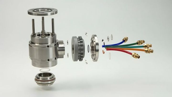
Hydraulic hoses carry pressurized fluid between components that may move relative to one another. They commonly contain an inner tube, reinforcement layers, and an outer protective cover. Materials and reinforcement depend on fluid compatibility, pressure, temperature, and environmental exposure.
Hoses, fittings, adapters, and seals must be compatible with the system's operating requirements. Damage, incorrect routing, excessive bending, abrasion, or unsuitable pressure ratings can lead to leakage or hose failure. Rigid pipes and metal tubing are also used where flexibility is unnecessary or where installation conditions favor fixed lines.
Recent Updates
Hydraulic technology continues to develop through improvements in electronic controls, energy efficiency, condition monitoring, and component design. Across 2024–2026, broader industrial trends have included the integration of sensors, digital monitoring, and electrohydraulic controls. Adoption varies by equipment type, manufacturer, application, and operating environment.
Smart Hydraulic Systems and Electronic Controls
Traditional hydraulic systems often rely on mechanical or pilot-operated controls. Modern designs may combine hydraulic components with electronic controllers, pressure sensors, position sensors, and proportional valves. These systems can adjust fluid flow and actuator movement according to operating conditions or programmed instructions.
For example, an electronically controlled hydraulic circuit can adjust cylinder movement based on load or position feedback. This approach can improve control precision in applications such as mobile machinery, industrial presses, and automated production equipment. However, electronic controls also introduce additional requirements for calibration, wiring, software configuration, and fault diagnosis.
Energy Efficiency and Condition Monitoring
Variable-displacement pumps can adjust their output to match changing system requirements. Load-sensing arrangements can also help reduce unnecessary flow and energy use under suitable operating conditions. Actual performance depends on circuit design, component condition, and how the machinery is operated.
Condition-monitoring systems may track pressure, temperature, vibration, fluid contamination, or operating cycles. Such information can help identify developing problems, although sensor readings require suitable interpretation and do not eliminate the need for physical inspections.
Hydraulic systems are also being designed for integration with electric machinery and automated equipment. These developments support more coordinated machine control, but conventional hydraulic components remain widely used because many applications require high force and reliable movement under demanding conditions.
Laws or Policies
Hydraulic systems are affected by machinery safety requirements, occupational health and safety rules, environmental regulations, and applicable engineering standards. The exact obligations depend on the equipment, its intended use, the workplace, and the country where it operates.
Industrial Safety Requirements in India
In India, industrial machinery may be subject to applicable occupational safety legislation, factory requirements, electrical safety provisions, and relevant state rules. The Occupational Safety, Health and Working Conditions Code, 2020, forms part of India's labor-law framework, with practical obligations depending on commencement notifications and applicable rules.
Hydraulic equipment used in factories, construction, lifting operations, or other regulated activities may also need to comply with requirements relevant to guarding, safe operation, inspection, maintenance, and worker training. The specific provisions applicable to an installation should be verified for its location and type of use.
Technical Standards and Environmental Considerations
Standards developed by the International Organization for Standardization (ISO) cover aspects of hydraulic fluid power, including system safety, component dimensions, terminology, and test methods. ISO 4413 is a key standard addressing general rules and safety requirements for hydraulic fluid power systems and their components. Applicable standards depend on the machinery and relevant regulatory framework.
Hydraulic fluid leaks can contaminate soil and water, while improper disposal of used fluid and filters can create environmental risks. Maintenance procedures should address leak prevention, suitable fluid handling, spill control, and disposal through appropriate channels under applicable environmental requirements.
Pressure-rated components, correct fluid selection, suitable guarding, and safe isolation procedures are important considerations. Pressurized hydraulic fluid can penetrate skin, and equipment may move unexpectedly if stored energy is not controlled. Inspection and repair should follow the machine manufacturer's documented safety procedures and be performed by appropriately trained personnel.
Tools and Resources
Several technical resources help explain hydraulic circuits, identify component functions, and support equipment planning. Their usefulness depends on the system design, available documentation, and the user's level of technical knowledge.
Hydraulic Calculators and Circuit Diagrams
Hydraulic calculators can estimate relationships among pressure, force, cylinder area, flow rate, and actuator speed. For an ideal cylinder, force is approximately equal to pressure multiplied by the effective piston area. Actual force may be lower because of friction, pressure losses, and other operating factors.
Circuit diagrams show how pumps, valves, cylinders, filters, reservoirs, and return lines connect. ISO hydraulic symbols are commonly used in technical drawings, allowing readers to recognize component functions without relying entirely on written labels.
Component Manuals and Technical References
Manufacturer manuals provide information about pressure ratings, fluid compatibility, installation requirements, maintenance intervals, and operating limits. Technical documentation from hydraulic equipment manufacturers such as Bosch Rexroth, Parker Hannifin, and Eaton can help readers understand component designs and system arrangements.
Useful resources include:
Hydraulic circuit diagrams and component identification charts.
Cylinder force and flow-rate calculators.
Hydraulic hose selection and compatibility guides.
Fluid cleanliness and contamination-control references.
Equipment inspection checklists and maintenance records.
Technical standards and machine-specific operating manuals.
These resources provide general technical information, but machine-specific documentation remains important because similar-looking components may have different pressure ratings, connections, or operating limitations.
FAQs
What are the main parts of a hydraulic system?
The main hydraulic system parts include a pump, valves, cylinders or motors, hoses or pipes, a reservoir, filters, and pressure-control components. Their arrangement depends on the machine and the work it performs.
What does a hydraulic pump do?
A hydraulic pump moves fluid through the circuit by converting mechanical energy into fluid-flow energy. Pressure develops as the fluid encounters resistance from the load and circuit components.
What is the difference between hydraulic valves and cylinders?
Hydraulic valves control fluid direction, flow, or pressure, while hydraulic cylinders convert fluid pressure into linear movement. Both components work together to control machinery.
How do hydraulic hoses function in a hydraulic system?
Hydraulic hoses transport fluid between components, particularly where flexibility is required. Their construction and pressure rating must suit the fluid, temperature, operating pressure, and installation conditions.
What causes common hydraulic system problems?
Common causes include fluid contamination, leaks, blocked filters, worn components, unsuitable fluid, and incorrect pressure settings. Diagnosis requires consideration of the machine's design, operating conditions, and manufacturer guidance.
Conclusion
Hydraulic system parts work together to transmit power, regulate fluid movement, and produce controlled mechanical force. Pumps, valves, cylinders, hoses, reservoirs, and filters each perform distinct functions within the hydraulic circuit. Electronic controls and condition monitoring are expanding the capabilities of some modern systems, while safety standards and environmental requirements continue to shape their design and operation. Understanding these components provides a useful foundation for learning how hydraulic machinery functions across industrial, agricultural, and construction applications.