Electro-Hydraulic Servo Systems Explained: Components, Working Principles, Applications and Benefits
Electro-hydraulic servo systems combine hydraulic power with electronic control to manage the movement, force, speed, and position of machinery. These systems use pressurized fluid to produce mechanical motion, while electronic controllers and servo valves regulate how the fluid moves through the circuit. They are used in industrial manufacturing, metal forming, aerospace equipment, testing machines, and other applications that require controlled mechanical movement.
Context
Electro-hydraulic servo systems combine hydraulic power with electronic control to manage the movement, force, speed, and position of machinery. These systems use pressurized fluid to produce mechanical motion, while electronic controllers and servo valves regulate how the fluid moves through the circuit. They are used in industrial manufacturing, metal forming, aerospace equipment, testing machines, and other applications that require controlled mechanical movement.
Hydraulic technology developed around the use of liquids to transmit force, while electronic control systems introduced more precise ways to regulate machine operation. Combining these technologies made it possible to control hydraulic actuators according to changing commands and measured operating conditions. An electro-hydraulic servo system typically includes a hydraulic pump, reservoir, actuator, servo valve, electronic controller, and sensors.
Main Components of Electro-Hydraulic Servo Systems
Each component performs a particular function within the system.
Hydraulic pump: Moves hydraulic fluid through the circuit and supplies the flow required for operation.
Hydraulic reservoir: Stores the fluid and provides space for cooling, air separation, and fluid management.
Servo valve: Regulates fluid direction and flow in response to electrical control signals.
Hydraulic actuator: Converts fluid pressure and flow into linear or rotary mechanical movement.
Electronic controller: Processes commands and sensor feedback to regulate system behavior.
Sensors and transducers: Measure variables such as position, pressure, velocity, or force.
Filters and pipelines: Carry fluid through the system and help limit contamination.
The exact arrangement depends on the machine's purpose. Some systems use a hydraulic cylinder for straight-line movement, while others use a hydraulic motor to produce rotation.
How Electro-Hydraulic Servo Systems Work
An electro-hydraulic servo system generally operates through a sequence of command, control, movement, and feedback. An operator or automated machine provides a target position, force, or speed. The controller compares the requested value with measurements from sensors and adjusts the electrical signal sent to the servo valve.
The valve changes the flow of hydraulic fluid to the actuator. The resulting pressure and fluid movement cause the actuator to move, apply force, or maintain a position. Sensors measure the resulting behavior and send information back to the controller, allowing further adjustments when necessary.
This feedback process is called closed-loop control. It helps the machine respond to changing loads and disturbances, although actual accuracy depends on the components, control settings, fluid condition, mechanical design, and operating environment.
Importance
Electro-hydraulic servo systems matter because many industrial processes require substantial force together with controlled motion. Purely mechanical systems may not provide the required flexibility, while electric drives may be less suitable for certain combinations of force, load, and operating conditions. Hydraulic power, combined with electronic regulation, provides an approach that can meet these requirements in suitable applications.
These systems affect manufacturing engineers, maintenance technicians, equipment operators, and industries that rely on controlled movement. They can help regulate press operations, material testing, machine positioning, and equipment movement where changes in load or position must be managed during operation.
Key Functions and Operational Characteristics
Several characteristics explain how electro-hydraulic servo systems are used in industrial equipment.
Motion control: Regulates actuator position, speed, and direction according to the control command.
Force control: Uses pressure measurements and system design to regulate the force applied by an actuator.
Load response: Adjusts operation when the mechanical load changes, within the system's design limits.
Repeatability: Supports repeated movements under similar conditions when the equipment is correctly maintained and calibrated.
Automation integration: Allows hydraulic equipment to receive commands from programmable controllers or industrial computer systems.
These characteristics do not mean every system delivers the same level of precision. Valve design, sensor quality, fluid temperature, mechanical friction, and control-loop tuning all influence performance.
Electro-Hydraulic Servo Systems Compared with Conventional Hydraulic Systems
| Feature | Conventional hydraulic control | Electro-hydraulic servo control |
|---|---|---|
| Main control method | Manual, mechanical, or basic electrical control | Electronic commands with feedback |
| Motion regulation | Depends on circuit and valve design | Can regulate position, speed, or force |
| Feedback | May be limited or absent | Commonly uses sensors in closed-loop designs |
| System complexity | Can be relatively simple | Usually requires additional electronics and calibration |
| Typical applications | General lifting and fluid-powered motion | Precision movement and dynamic load control |
The distinction is not absolute. Conventional hydraulic equipment can include electronic controls, and not every electro-hydraulic arrangement uses a closed feedback loop. The control architecture determines the system's actual capabilities.
Recent Updates
Developments in electro-hydraulic servo systems increasingly focus on electronic integration, energy management, condition monitoring, and improved control software. Across the 2024–2026 period, broader industrial automation trends have encouraged manufacturers to connect hydraulic equipment with digital monitoring and machine-control platforms. Specific capabilities vary by equipment type and manufacturer.
Digital Control and Industrial Automation
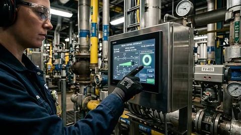
Modern controllers can exchange information with programmable logic controllers (PLCs), industrial computers, and supervisory control systems. This integration allows operators to coordinate hydraulic movement with other manufacturing steps, record operating measurements, and adjust control parameters where the system permits.
Some systems also use digital diagnostic tools to identify abnormal pressure patterns, temperature changes, or deviations in actuator movement. These measurements may help maintenance teams investigate potential problems before they interrupt production. However, monitoring software cannot identify every fault, and its usefulness depends on sensor coverage and the quality of the collected data.
Energy Efficiency and Condition Monitoring
Hydraulic systems can consume significant energy when pumps continue supplying more flow or pressure than a process requires. Variable-speed pump drives, demand-based control, improved hydraulic circuit design, and energy recovery methods can reduce unnecessary energy use in suitable applications.
Condition monitoring is another area of development. Sensors can track fluid temperature, pressure, vibration, and other operating variables to help assess equipment condition. Regular inspection, appropriate filtration, and fluid management remain important because electronic control does not eliminate leakage, contamination, seal wear, or mechanical damage.
Laws or Policies
Electro-hydraulic servo systems are affected by machinery safety requirements, electrical safety rules, pressure-system standards, environmental regulations, and workplace procedures. Applicable requirements depend on the equipment, its operating pressure, its installation, and the country in which it is used.
Industrial Safety Requirements in India
In India, industrial machinery may fall under applicable provisions of the Occupational Safety, Health and Working Conditions Code, 2020, relevant rules, and other legislation in force. Requirements can vary according to implementation arrangements, the establishment, and the type of industrial activity. Applicable state factory rules and electrical safety requirements may also be relevant.
Hydraulic equipment can create hazards involving high-pressure fluid, unexpected actuator movement, stored energy, hot components, and electrical controls. Risk assessment, guarding, pressure relief arrangements, suitable isolation procedures, and trained personnel are important parts of safe operation. Maintenance should account for residual pressure even after the main power source has been switched off.
Technical Standards and Environmental Considerations
Standards from the International Organization for Standardization (ISO) address areas such as hydraulic fluid power, system safety, and contamination control. For example, the ISO 4413 series covers general rules and safety requirements for hydraulic fluid power systems and their components. Standards may be voluntary or become applicable through legislation, contracts, or other requirements.
Environmental rules may affect hydraulic fluid selection, leakage prevention, storage, and disposal. Used hydraulic oil should be handled according to applicable waste-management requirements rather than released into soil or drainage systems. Equipment designers and operators must consider the rules relevant to their installation and operating location.
Tools and Resources
Technical tools and reference materials help engineers understand, configure, monitor, and maintain electro-hydraulic servo systems. The appropriate resource depends on whether the task involves initial design, troubleshooting, safety assessment, or routine inspection.
Design and Simulation Tools
Engineering software can support hydraulic circuit design, actuator calculations, dynamic modeling, and control-system simulation. Tools such as MATLAB and Simulink can be used for modeling control loops and evaluating system responses. Hydraulic component manufacturers may also provide configuration software, technical manuals, and performance data for specific equipment.
Common engineering calculations include:
Cylinder force: Approximate theoretical force equals pressure multiplied by effective piston area.
Actuator speed: For a hydraulic cylinder, approximate speed equals fluid flow divided by effective piston area.
Hydraulic power: Ideal hydraulic power is pressure multiplied by volumetric flow rate, with appropriate unit conversion.
Actual output is affected by friction, leakage, pressure losses, and mechanical efficiency. These calculations are useful for understanding relationships between system variables, but equipment selection requires consideration of operating limits and safety factors.
Monitoring and Maintenance Resources
Pressure gauges, temperature sensors, flow meters, position transducers, and diagnostic software can help assess system behavior. Maintenance records can track fluid changes, filter replacement, leakage observations, calibration, alarm history, and component inspections.
Useful reference sources include ISO publications, the Bureau of Indian Standards, equipment manuals, and technical documentation from hydraulic component manufacturers. Documentation should match the installed model and configuration because operating limits and maintenance procedures differ between systems.
FAQs
What is an electro-hydraulic servo system?
An electro-hydraulic servo system combines hydraulic power with electronic feedback control to regulate motion, force, speed, or position. It commonly uses a servo valve, actuator, controller, and sensors.
How does an electro-hydraulic servo valve work?
A servo valve responds to an electrical control signal by regulating hydraulic fluid flow or direction. This changes the movement of the connected actuator according to the circuit design and operating conditions.
What are the main applications of electro-hydraulic servo systems?
Applications include industrial presses, injection molding equipment, aerospace control equipment, material-testing machines, metal-forming machinery, and precision positioning systems.
What are the main benefits and limitations of electro-hydraulic servo systems?
Potential benefits include high force capability, adjustable motion, and closed-loop control. Limitations can include fluid leakage, contamination sensitivity, heat generation, system complexity, and the need for regular maintenance.
How are electro-hydraulic servo systems maintained?
Maintenance commonly includes checking fluid condition, filters, hoses, seals, connections, sensor readings, and valve operation. Safe isolation and pressure release must follow the equipment manufacturer's procedures and applicable workplace rules.
Conclusion
Electro-hydraulic servo systems combine hydraulic force with electronic control to regulate machine movement and operating conditions. Their performance depends on component selection, feedback design, fluid quality, calibration, and maintenance. Digital monitoring and automation integration are expanding the ways these systems are used in industrial equipment. Understanding their operating principles and applicable safety requirements helps explain their role in modern manufacturing and other demanding mechanical applications.

You May Also Like