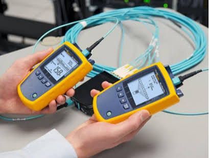
Fiber Optic Tester Overview: Device Types, Testing Processes, Measurements and Fiber Network Applications
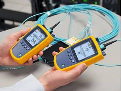
A fiber optic tester is a measurement device used to examine the condition and performance of optical fiber links. Fiber networks transmit information through pulses of light rather than electrical signals, so specialized testing equipment is needed to identify optical losses, connection problems, breaks, reflections, and other conditions that can affect network performance.
Context
Fiber optic testing developed alongside the expansion of optical communication systems. As fiber cables became widely used in telecommunications, data centers, broadband networks, industrial communication, and other applications, technicians needed reliable methods for checking installed cables and individual components.
A modern fiber optic tester can refer to several different instruments. An optical power meter measures the amount of optical power reaching a particular point, while a light source provides a known optical signal for loss measurements. An optical time-domain reflectometer, commonly called an OTDR, sends optical pulses into a fiber and analyzes reflected and backscattered light to identify events along the cable.
Other instruments include visual fault locators, optical loss test sets, fiber inspection systems, and optical spectrum analyzers. Each device measures different characteristics, so a complete fiber testing process may involve more than one instrument.
Why fiber testing is different from electrical testing
Copper networks can be tested using electrical properties such as resistance, voltage, and continuity. Optical fiber instead depends on light transmission through a glass or polymer-based structure.
Important characteristics therefore include attenuation, optical return loss, connector performance, splice loss, wavelength, and the physical condition of the fiber end face.
The testing method also depends on the type of network. Single-mode fiber and multimode fiber have different characteristics and may require different test settings, wavelengths, and procedures.
Importance
Fiber optic testing matters because an optical network can contain problems that are not immediately visible. A cable may appear physically intact while excessive attenuation, a damaged connector, a poor splice, or a bend is reducing the amount of light reaching the receiving equipment.
Testing is used during installation, commissioning, troubleshooting, maintenance, and network upgrades. It can help establish whether an installed link meets the expected optical requirements before it becomes part of an operating network.
Common reasons for testing
Fiber testing can be used to:
- Measure optical loss across a link
- Locate breaks or high-loss events
- Examine connectors and fiber end faces
- Identify excessive bends or damaged sections
- Verify splice performance
- Measure optical return loss
- Document baseline measurements
- Investigate intermittent or degraded network performance
The appropriate measurement depends on the question being investigated. An optical power meter can determine how much optical power is received, while an OTDR can provide information about where significant events occur along the fiber.
Main fiber optic tester types
Different instruments perform different functions.
| Tester or instrument | Primary measurement or function | Common application |
|---|---|---|
| Optical power meter | Received optical power | Link-loss and power measurements |
| Optical light source | Controlled optical signal | Loss testing with a power meter |
| Optical loss test set | Optical insertion loss and related measurements | Installation and certification |
| OTDR | Distance, reflections and event locations | Fault finding and link characterization |
| Visual fault locator | Visible red-light indication | Locating breaks and routing faults |
| Fiber inspection probe | Connector end-face condition | Connector inspection |
| Optical spectrum analyzer | Optical spectrum characteristics | Advanced optical network analysis |
No single instrument performs every fiber measurement. Testing equipment is normally selected according to the network architecture, fiber type, wavelength, required measurement, and testing stage.
Recent Updates
Fiber testing practices continue to evolve as optical networks become more complex and are deployed across data centers, access networks, broadband infrastructure, industrial environments, and long-distance communication systems.
One notable development has been the continued refinement of international measurement standards. IEC 61280-4-2:2024 specifies procedures for measuring attenuation and optical return loss in installed single-mode fiber cabling plants. Its scope includes cables containing fibers, connectors, adapters, splices, and other passive components, including installations in data centers and outside-plant environments.
IEC 60793-1-40:2024 also provides standardized methods for measuring optical-fiber attenuation. The methods include cut-back, insertion-loss, backscattering, and spectral-attenuation approaches.
Developments in fiber measurement
ITU-T Recommendation G.650.1 was approved in 2024 and remains in force. It defines measurement methods for linear, deterministic characteristics of single-mode optical fibers and cables, with applications that include factory measurements and characterization of certain optical components.
The broader ITU-T work programme also shows continuing study of fiber characteristics and test methods, including revisions concerning single-mode fiber, bend-insensitive fiber, and other optical-fiber technologies.
Another development is the increasing use of testing in passive optical networks. IEC 61280-4-3 describes methods for measuring attenuation, optical return loss, and optical power in installed single-mode passive optical networks, including approaches based on light sources, power meters, and OTDR measurements.
These developments reflect a broader trend toward standardized measurements, digital test records, automated analysis, and more detailed documentation of fiber links.
Laws or Policies
Fiber optic testers are generally influenced by technical standards, telecommunications requirements, electrical and workplace safety rules, and regulations concerning communications infrastructure. The exact legal requirements vary according to the country, network type, installation environment, and organization responsible for the infrastructure.
International standards from organizations such as IEC and ITU-T provide technical frameworks for optical-fiber characteristics and measurement methods. These standards are not necessarily laws by themselves, but they can be referenced by national regulations, engineering specifications, procurement documents, network operators, and installation requirements.
Standards and measurement practices
ITU-T G.650.1 provides definitions and test methods for several characteristics of single-mode optical fiber and cable.
IEC 61280-4-2:2024 addresses attenuation and optical return loss measurements for installed single-mode cabling plants.
For passive optical networks, IEC 61280-4-3 provides procedures covering attenuation, optical return loss, and optical power measurements.
Network projects may additionally specify requirements for test documentation, acceptable loss limits, reference cords, connector inspection, calibration, and technician procedures. Consequently, a testing process should be interpreted according to the applicable project specification and technical standard rather than a single universal threshold.
Tools and Resources
A fiber testing workflow normally combines instruments and supporting resources. The selection depends on whether the objective is installation verification, troubleshooting, maintenance, certification, or laboratory measurement.
Optical power meter and light source
An optical power meter measures the optical power reaching the measurement point. When combined with a controlled light source, it can be used to determine insertion loss across a fiber link.
This approach is useful when the objective is to understand the total loss between two points rather than locate each event along the cable.
OTDR
An OTDR sends optical pulses into the fiber and analyzes backscattered and reflected light. The resulting trace can show the approximate location of connectors, splices, bends, breaks, and other events that produce measurable changes.
OTDR measurements require appropriate settings for fiber type, wavelength, pulse width, range, and averaging. Launch and receive fibers may also be used to help evaluate the first and last connectors of a link.
Fiber inspection tools
Inspection probes use magnification and imaging to examine connector end faces. Contamination, scratches, pits, or other physical conditions can affect optical performance.
Inspection is particularly relevant because contamination at a connector can influence measurements and may also affect the mating surfaces of connected components.
Testing documentation
A useful fiber test record can include:
- Cable or link identification
- Fiber number
- Fiber type
- Wavelength
- Test direction
- Reference method
- Optical loss measurement
- OTDR trace, where applicable
- Test equipment identification
- Test conditions
- Date and location
- Pass or fail criteria specified for the project
Keeping consistent records makes it easier to compare measurements during installation and later maintenance.
Testing Processes and Measurements
Basic optical loss testing
A typical loss measurement uses a calibrated optical source and a power meter. The source introduces a known signal into the fiber, and the meter measures the resulting power at the receiving end.
The difference between the reference measurement and the received measurement represents the optical loss under the selected test conditions. Connectors, splices, fiber length, bends, and other components can contribute to the measured result.
OTDR testing
OTDR testing provides a different type of information. Instead of simply measuring total loss, the instrument creates a distance-based trace showing changes in backscatter and reflections.
An OTDR can help identify the approximate location of an event, but interpretation requires attention to factors such as dead zones, pulse width, reflectance, launch conditions, and the characteristics of the fiber being tested.
Important measurements
Several measurements commonly appear in fiber testing:
- Attenuation: reduction in optical signal power as light travels through the fiber.
- Insertion loss: optical power reduction caused by inserting a component or link into an optical path.
- Optical return loss: measurement associated with reflected optical power returning toward the source.
- Reflectance: amount of light reflected by a specific event, such as a connector.
- Distance: estimated location of an event along the fiber.
- Optical power: amount of optical energy measured at a particular point.
Different measurements answer different questions, which is why fiber network testing often involves multiple instruments.
FAQs
What is a fiber optic tester used for?
A fiber optic tester is used to measure and investigate the performance of optical fiber links. Depending on the instrument, it can measure optical power, attenuation, insertion loss, optical return loss, or the location of events along a fiber.
What is the difference between an optical power meter and an OTDR?
An optical power meter measures optical power at a specific point. An OTDR analyzes reflected and backscattered light to create a distance-based trace, helping identify the approximate location of events such as splices, connectors, bends, and breaks.
How is fiber optic cable testing performed?
Fiber optic cable testing can involve connector inspection, reference measurements, optical loss testing, and OTDR testing. The exact sequence depends on the network type, fiber type, applicable standard, and project requirements.
What measurements does a fiber optic tester provide?
Depending on the device, measurements can include optical power, attenuation, insertion loss, optical return loss, reflectance, and event distance. A particular tester may not provide every measurement.
Why is fiber optic testing important for network applications?
Testing helps establish the optical condition of a network link and can identify problems that may not be visible from the outside of a cable. It is used across telecommunications, data centers, broadband networks, industrial networks, and other fiber-based communication environments.
Conclusion
A fiber optic tester is a measurement instrument used to examine optical-fiber performance, locate faults, and document network characteristics. Different instruments, including optical power meters, light sources, loss test sets, OTDRs, and inspection systems, address different testing requirements. Recent international standards have continued to refine measurement methods for attenuation, optical return loss, and single-mode fiber characteristics. Proper testing therefore depends on the fiber type, network architecture, measurement objective, applicable technical standard, and conditions of the installation.