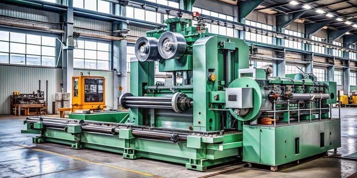
Automatic Lathes Guide: Machine Types, Cutting Operations, Features and Industrial Applications
Automatic lathes are machine tools designed to rotate a workpiece while cutting tools shape its surface. They are widely used for producing cylindrical, threaded, grooved, drilled, and other turned components with limited manual intervention. An automatic lathe can perform several machining steps according to a programmed or mechanically controlled sequence.
The development of automatic lathes is closely connected with the growth of industrial manufacturing. Traditional lathes require an operator to control many cutting movements manually, while automatic systems can coordinate repeated operations through mechanical mechanisms, cams, numerical controls, or computer-based systems.
Automatic lathes are commonly used when manufacturers need to produce many similar components with consistent dimensions. Typical parts include shafts, pins, bushings, screws, fittings, connectors, and other cylindrical components used in machinery, automotive equipment, electronics, and industrial systems.
How Automatic Lathes Work
The basic operating principle is similar to other turning machines. A workpiece is held by a chuck, collet, spindle, or another holding arrangement and rotated around its central axis. A cutting tool then moves against the rotating material to remove small amounts of material.
Depending on the machine design, automatic controls can manage operations such as feeding the material, moving cutting tools, changing tools, forming threads, creating grooves, and removing completed components. The exact sequence depends on the machine configuration and production requirements.
Main Components
An automatic lathe generally contains several important components:
- Spindle: Rotates the workpiece at a selected speed.
- Chuck or collet: Holds the material securely during machining.
- Tool holder: Positions cutting tools relative to the workpiece.
- Carriage or slide system: Controls tool movement.
- Feed mechanism: Moves material or tools according to the machining sequence.
- Control system: Coordinates machine movements and operating parameters.
- Coolant system: May be used to manage heat and remove machining debris.
The arrangement varies between machine types, so the operating method of one automatic lathe may differ considerably from another.
Importance
Automatic lathes matter because many industrial products contain small, precisely shaped components that require repeated machining operations. Producing these parts manually can involve substantial operator involvement, particularly when the same component must be manufactured repeatedly.
Automation helps organize repetitive machining movements and can provide consistent production conditions. It can also reduce the amount of direct manual control needed during individual machining cycles.
Industrial Applications
Automatic lathes are used across several manufacturing sectors. Common applications include:
- Automotive components such as shafts, pins, bushings, and fittings
- Electrical and electronic components
- Hydraulic and pneumatic fittings
- Industrial machinery parts
- Medical equipment components
- Fasteners and threaded components
- Instrumentation components
- Small mechanical assemblies
The appropriate machine depends on factors such as material type, component dimensions, required operations, production quantity, and dimensional requirements.
Production Challenges
Although automatic machining can reduce repetitive manual work, several factors still influence the quality of finished components. Tool wear, incorrect cutting parameters, material variation, vibration, workholding problems, and machine alignment can affect machining results.
Operators and production engineers therefore need to understand the relationship between spindle speed, feed rate, cutting depth, tool geometry, material properties, and machine rigidity. Regular inspection of components can help identify dimensional changes during production.
Recent Updates
Recent developments in automatic lathes have focused on digital controls, automation, monitoring, energy management, and integration with broader manufacturing systems. Modern equipment increasingly combines conventional turning principles with computerized control systems.
CNC and Digital Control
Computer numerical control, commonly called CNC, has become an important part of modern automatic turning. CNC systems allow machining instructions to be stored digitally and executed through controlled movements of machine axes.
Compared with mechanically controlled automatic lathes, CNC systems can provide greater flexibility when component designs or machining sequences change. They are commonly used for applications requiring multiple operations or digitally managed production programs.
Automation and Material Handling
Automatic lathes can also be connected with material-feeding and handling equipment. Bar feeders, automatic loading systems, part collectors, and robotic handling systems can help coordinate material movement around the machining process.
These developments are part of a broader movement toward connected manufacturing. Machines may exchange production information with monitoring systems, manufacturing software, or factory-level data platforms.
Monitoring and Condition Tracking
Machine monitoring has also become more common. Sensors and software can track information such as spindle conditions, operating cycles, vibration, temperature, and tool usage.
Such information can help production teams identify unusual operating conditions and investigate potential causes of dimensional or process changes. The availability of monitoring features varies by machine and control system.
Laws or Policies
The operation of automatic lathes is affected by workplace safety requirements, machinery safeguards, electrical rules, and environmental regulations. Because requirements vary by country and industrial setting, manufacturers and operators need to follow the rules applicable to their location.
Workplace Safety in India
In India, industrial machinery safety is influenced by occupational safety legislation and applicable state and central requirements. The Occupational Safety, Health and Working Conditions Code, 2020 provides a broader legal framework covering occupational safety and working conditions, although implementation and applicable requirements can depend on the establishment and relevant rules.
Machine operators generally need appropriate training and must follow established procedures for machine guarding, emergency controls, electrical safety, maintenance, and personal protective equipment where required.
Machine Guarding and Safe Operation
Rotating components, cutting tools, chips, and moving machine parts can create physical hazards. Guards and protective devices are therefore important parts of machine design and workplace safety.
Common safety practices include:
- Keeping protective guards in their intended position
- Using appropriate eye and face protection where required
- Keeping loose clothing away from rotating components
- Following machine-specific operating instructions
- Stopping and isolating equipment before maintenance activities
- Keeping the work area clear of chips and accumulated material
Specific requirements should be checked against current national, state, and workplace regulations rather than relying on general guidance alone.
Tools and Resources
Several resources can help readers understand automatic lathes and turning processes. Machine manuals are particularly useful because they explain the controls, operating sequence, maintenance requirements, and safety features of a specific machine.
Technical Resources
Useful resources include:
- CNC programming references for turning operations
- Machining handbooks and engineering reference tables
- Cutting-tool manufacturer technical guides
- Machine-tool manufacturer manuals
- Industrial training materials
- CAD/CAM software documentation
- Government workplace-safety resources
- Engineering calculators for spindle speed and feed calculations
A basic machining reference can help explain terms such as cutting speed, feed rate, depth of cut, tool geometry, tolerance, and surface finish.
Basic Machining Calculations
Machining calculations can help determine suitable operating parameters. For example, spindle speed is related to cutting speed and workpiece diameter. A commonly used relationship is:
Spindle Speed = Cutting Speed × 1000 ÷ π × Diameter
The appropriate units and material-specific parameters need to be considered when applying such calculations. Actual machine settings should follow the machine documentation, tooling information, and applicable production requirements.
Comparison of Automatic Lathe Types
| Machine Type | Control Method | Common Application |
|---|---|---|
| Single-spindle automatic lathe | Mechanical or electronic | Repeated small components |
| Multi-spindle automatic lathe | Multiple rotating spindles | High-volume component production |
| CNC automatic lathe | Computer numerical control | Flexible precision turning |
| Swiss-type lathe | Guide bushing and CNC control | Small, slender components |
| Screw machine | Mechanical or CNC control | Repeated turned components |
Cutting Operations
Automatic lathes can perform several machining operations depending on their tooling and configuration. Each operation removes or shapes material in a different way.
Turning
Turning reduces the outside diameter of a rotating workpiece. A cutting tool moves along the material to create a cylindrical surface.
Facing
Facing produces a flat surface at the end of a component. The cutting tool moves across the end face while the workpiece rotates.
Threading
Threading creates a helical groove on an external or internal surface. Automatic and CNC lathes can coordinate tool movement with spindle rotation to produce specified thread forms.
Grooving and Parting
Grooving creates a narrow recess in the workpiece. Parting, sometimes called cutoff machining, separates a finished component from the remaining material.
Drilling and Boring
Drilling creates a hole, while boring enlarges or refines an existing hole. These operations can often be incorporated into an automatic machining sequence when suitable tooling is available.
Machine Types and Features
Different automatic lathe designs are intended for different component sizes, shapes, and production requirements.
Single-Spindle Automatic Lathes
A single-spindle automatic lathe uses one primary spindle to rotate the workpiece. These machines can perform multiple cutting operations during a production cycle.
Multi-Spindle Automatic Lathes
Multi-spindle machines contain several spindles that can hold multiple workpieces or move through different machining stages. This configuration can allow several operations to occur within an organized production cycle.
CNC Automatic Lathes
CNC automatic lathes use computer-controlled instructions to manage tool movement and machining operations. They are suitable for applications where machining programs need to be changed or adjusted for different component designs.
Swiss-Type Automatic Lathes
Swiss-type machines support slender workpieces close to the cutting area, commonly through a guide-bushing arrangement. They are frequently associated with small-diameter components that require controlled support during machining.
Material Considerations
Automatic lathes can machine a range of materials, although tooling and operating conditions must be matched to the material being processed. Common materials include steel, stainless steel, aluminum, brass, copper alloys, and certain engineering plastics.
Material hardness, thermal behavior, ductility, and machinability can influence tool selection and cutting parameters. Different materials can also produce different chip shapes and heat levels during machining.
FAQs
What is an automatic lathe?
An automatic lathe is a turning machine that performs a sequence of machining operations with limited manual control during each production cycle. It can be mechanically controlled or computer controlled depending on its design.
What are the main automatic lathe machine types?
Common automatic lathe machine types include single-spindle, multi-spindle, CNC, and Swiss-type machines. Each configuration has different capabilities for component size, machining operations, and production arrangements.
What cutting operations can automatic lathes perform?
Automatic lathes can perform turning, facing, threading, grooving, parting, drilling, and boring when suitable tooling and machine configurations are available.
What materials can automatic lathes machine?
Automatic lathes can process materials such as steel, stainless steel, aluminum, brass, copper alloys, and selected engineering plastics. The appropriate tooling and operating parameters depend on the material.
How are CNC automatic lathes different from traditional automatic lathes?
CNC automatic lathes use computer-controlled instructions to coordinate machine movements. Traditional automatic lathes may use mechanical systems, cams, or other control arrangements for repeated machining sequences.
Conclusion
Automatic lathes are machine tools used to produce repeated turned components through organized machining sequences. Different configurations, including single-spindle, multi-spindle, CNC, and Swiss-type machines, address different manufacturing requirements. Modern developments increasingly involve digital controls, automated material handling, and machine monitoring. Safe operation also depends on appropriate training, machine guarding, maintenance procedures, and compliance with applicable workplace requirements.